Using Trimble Business Center
Trimble Business Center is a highly versatile tool for preparing data for site works and road construction, and is an ideal tool for preparing data for use with SiteVision. It can import data from a broad range of formats, and combine data from different sources such as GIS data from an existing database with topographical surveys and design data.
Trimble Business Center version 5.10 or later has an export option for SiteVision, on the Construction export tab.
-
Before you start the export, set up your external services profile so that you can save data remotely on Trimble Connect; select File / Options / External Services-Profiles. Create a service profile for Trimble Connect. For more information refer to the Trimble Business Center documentation.
-
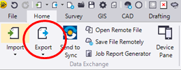
On the Home tab, tap Export.
-
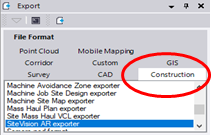
In the Export pane select Construction.
-
Select the SiteVision AR exporter file format.
-
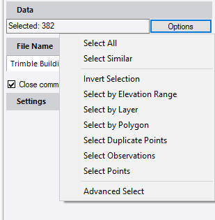
Using the standard selection tools in Trimble Business Center select the data you want to export.
-
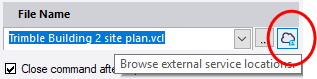
When you have selected your data click on the cloud symbol by the file name to save the exported data to Trimble Connect.
-
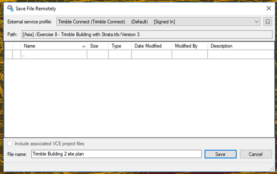
In the Save File Remotely window, select the server location, project, and folder on Trimble Connect and name the file you want to save, then click Save.
-
At the bottom of the Export tab, click Export. Trimble Business Center will export the files.
-
In the SiteVision app, tap
 /
/  Load Model /
  Trimble Connect. Navigate to the project and folder you saved the model to then select the model.
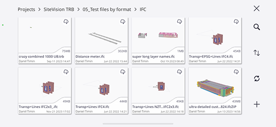
When exporting using the SiteVision AR exporter four files are created and stored in the selected Trimble Connect project folder:
-
The Trimble Site Calibration file. If the Trimble Business Center project contains an applied Site Calibration, the exporter creates a .CAL file. For a project without an applied Site Calibration, it creates a .JXL file. Both files include any selected Control Points.
-
A VCL file of the selected data for use with other Trimble products such as Siteworks and Earthworks.
-
A TRB file, which is the model optimized for high speed visualization performance for use by SiteVision.
-
An FXL file, which contains the feature definition library for the project including defined Feature Codes.
SiteVision supports the following elements from Trimble Business Center using the SiteVision AR exporter; exported objects contain attribute information:
-
Points
-
Lines (including Arcs/Circles)
-
Surfaces
-
Utilities
-
Corridors
-
Alignments
TIP – If you want to visualize fully rendered models of pipe networks from Trimble Business Center, export the network as a LandXML file and also export a JXL file with the same name using the Trimble Field Software exporter option.
There are some additional limitations and elements that are not supported by the Trimble SiteVision AR Exporter:
-
Grid Lines
-
CAD Blocks. These are not supported and not included in the export.
TIP – If you need to export blocks, you can explode them.
-
Point cloud regions. These are not supported and cause the exporter to crash if they are included in the export selection.
-
IFC Models are not supported and not included in the export. You can export these separately using the IFC exporter in the CAD tab of the Export window.
-
When an object is selected for export, all dependent objects are also included in the export. For example, if a draped line is exported, the 2D line that defines the draped line is also included in the export (you can explode a draped line to create a discrete, 3d linestring). This also occurs with surfaces if a surface is defined by another surface, e.g. a surface tie or utility trench; all related surfaces will be included in the export.
-
Trimble Business Center Utilities Module:
-
Utility nodes are treated as a dependent object of a utility pipe run; exporting a pipe will also export the associated nodes.
-
Be mindful that some of the 3D blocks used to represent utility nodes can be quite complex. For larger utility networks it may be necessary to select node representations that are geometrically simple, or SiteVision performance may be impacted.
-
Visualizing cut/fill map images and images
SiteVision allows you to drape images onto surface models using tools in Trimble Business Center. The key elements required are:
-
A Trimble Terrain Model (TTM) file containing a model of the surface that you want to drape the image onto.
-
A Trimble Site Calibration file (JXL, DC or CAL) to georeference the TTM and images.
-
Georeferenced images such as a PGN file with its associate PGW georeference file.
To create the TTM file:
-
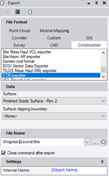
Select the Export option.
-
Select the Construction tab.
-
Select TTM Exporter.
-
Select the surface that you want to use for draping.
-
Click the cloud icon and select the Trimble Connect project and folder to place the TMM in.
-
Click Save and then Export.
To create the Trimble Site Calibration file if you do not already have one, see Creating a Trimble Site Calibration file.
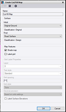
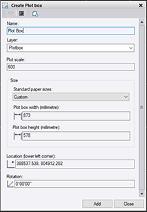
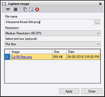
To create a cut/fill image:
|
|
|
|
|
|
NOTES –
-
You can have multiple images stored with the TTM, so if higher resolution is required, create multiple cut/fill map images at higher resolution.
-
The image name becomes the layer name in SiteVision.
-
You can view one layer/image at a time, draped on the surface.
-
Images can be any form of image, such as historical imagery, cut/fill maps, pass count maps, or PDF plans, provided that the images are georeferenced.
For more information see the video Data prep – TBC 03 – Thematic maps at the resource page of sitevision.trimble.com.