Workflows for Architects and Landscape Architects: Using SketchUp
Trimble SketchUp is a highly versatile 3D modelling software that generates 3D models in the .SKP format. To use the 3D model in SiteVision you will need to georeference the model in some way to connect the model co-ordinate system to the real world.
When preparing your SketchUp models, note the following:
- For best visualization in SiteVision apply material textures to individual object faces.
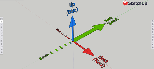
- The Green axis is the North-South axis.
- Do not create multiple surfaces at the same location, such as two different faces on a wall. When models with two surfaces in the same location are drawn by SiteVision the display engine will try to draw both surfaces and their assigned colors which will result in flickering of the model in the area of that surface.
- Organize your model by using components. You can create a component by selecting an object and right-clicking to access the Create Component function. Organize your components by layer to allow simpler selection/viewing in SiteVision.
- To display attributes you must be using SketchUp Pro. From the Components created right-click on your component and select Dynamic Components\Component attributes. Then add the attributes as required. Refer to the on-line tutorial at Sitevision.trimble.com for more information.
NOTE – The Geo-location function within SketchUp will not automatically georeference the model in the real world with SiteVision. You must use one of the methods described below.
SiteVision supports
| Method | Ease in office | Ease in the field | Accuracy | Stability |
|---|---|---|---|---|
| Automatic Placement | Most complex |
Easiest No field work |
Best | Best |
| Measured Placement |
Easy No office work |
Easy | Good | Best |
Measured placement is ideal for users who are unfamiliar with co-ordinate systems or for designers that have used an arbitrary reference (e.g. a co-ordinate origin of 0,0,0).
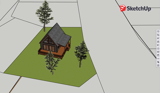
When using the measured placement method, it is important to include in your design some reference points that you can use to position the model on site. Ideally, these will be points that can be referred to throughout the construction process. In the example below the designer has added the property lines to the model:

When doing the measured placement, measurements are made with the SiteVision system at two property corners; these are used to position and orientate the model on site.
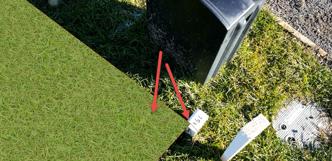
In the image below a measurement was made with the SiteVision GNSS at property corner 151, and this property corner was selected in the model to position the model correctly. The arrows show the land parcel surface and property corner in the SketchUp model:

Having a single depth surface such as the property boundary makes setting the elevation simple because both the top and bottom of the model in that location are at the same elevation.
When you do a measured placement the results are stored in Trimble Connect and are available for any future visits to site, for you and any others who use the model and access it from your Trimble Connect project. This means that the measured placement procedure only needs to be done once, and the model is automatically located in the same place for all future use. See Placing a model: Measured Placement for more details.
TIP – Having a single surface such as the existing ground makes setting the elevation simple because both the top and bottom of the model in that location are at the same elevation.

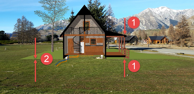
- 1 If your reference point is in an area with multiple surfaces you must select the top or bottom of the model during measured placement, or the model will be drawn at the wrong elevation.
- 2 With a single surface the top and bottom of the model are at the same elevation.
The Automatic Placement method requires two additional pieces of software to automatically georeference a model:
- The SiteVision extension for SketchUp available from the SketchUp Extension Warehouse. See https://extensions.sketchup.com/extension/090b20c2-804f-4c90-bb0a-fb217d761fb8/trimble-site-vision-ar-exporter-for-sketch-up
- A copy of Trimble Business Center, or access to a georeferenced file from a Surveyor or other Trimble Business Center user in the Trimble JXL, DC, or CAL file format.
To generate models that are automatically placed:
- Prepare your model in SketchUp with the Green axis as your North orientation.

- When the model is complete, save it.
- Enter the origin coordinates from within SketchUp using the SiteVision AR exporter; tap
 , enter the origin coordinates and click Ok to apply them to the model.
 - In the SiteVision AR exporter tap
 to export the model for SiteVision. Save the file under a different name, such as MyModel-for-SiteVision.SKP
 - Drag and drop your SKP file into your Trimble Connect project.
- Create or obtain the JXL file for georeferencing the model from Trimble Business Center.
- Rename the JXL file to exactly match the .SKP file name, except for the extension. For example if the .SKP file is called MyModel-for-SiteVision.skp, then the JXL file should be called MyModel-for-SiteVision.jxl.
- Drag and drop the JXL file into the same project folder and the design model.
