Using the Profile app 
The Profile tool allows you to design linear trenches, bunds, etc, compatible with Trimble Earthworks and Trimble Business Center. The designs are stored both locally on the device and synchronised to Trimble Connect.
TIP – Using the Trimble File Flipper app, you can transfer a design directly to your Trimble Earthworks machine control system in the field.
You can design profiles using GNSS ( ), Real World (
 /
/  /
/  ) or Model (
 ) based measurements. For best results, use GNSS measurement mode.
To design a profile, you measure the first point of the alignment, draw the profile template on a grid, then measure additional points to extend the profile's alignment in the required direction and distance.
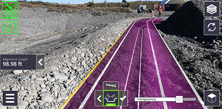
A completed profile alignment is shown as:
-
a yellow line which corresponds to the alignment (following the measured points)
-
white lines which represent the borders / changes in the profile's angles
-
a purple surface
-
Measure a point, which is the first point of the profile's alignment.
A grid appears on the screen. You may need to step back to fully see the grid.
-
Tap points on the grid as needed to draw the profile template.
NOTE – You can also enter values in the panel on the left of the screen.
TIP – To discard a profile template's point, double-tap it. To move a point, tap-hold and drag it in the grid. You can also edit its values in the side panel.
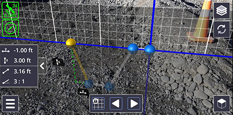
By default, points are snapped to the nearest corresponding point on the grid. To turn off the 'snap' functionality, tap
 to 'unlock' the grid and place points freely.
 -
When the profile template is complete, tap
 .
. -
Walk in the direction that the profile is to extend in (i.e. the alignment), and measure a second point. The profile will extend from the first measured point to the second measured point.
-
Walk and measure additional points as needed.
TIP – To discard a point in the profile's alignment, double-tap it.
TIP – To insert a point after a previously measured point, tap the previously measured point to 'activate' it, then measure your new point. The new point is inserted after the 'activated' point.
NOTE – If you turn at a sharp angle, a curve is created in the design.
-
You can adjust the elevation of the profile alignment. Tap
 to see the Edit Alignment Elevation window, and edit if required the Start Elevation, End Elevation, Grade, Start Offset, and End Offset.
The Start Elevation, End Elevation, and Grade fields are all linked; editing one requires another to change accordingly. When you edit one of these fields, the other field that you most recently edited stays fixed, while the remaining field changes. Initially, the Start Elevation is considered the most recently edited.
Tap Apply to save your edits.
In the window, the red line (the line between the first and last point of the alignment) represents the alignment's grade.
-
When you have created the profile as needed, tap
 to give the profile a name. Tap Finish to save it.
-
The surface and associated linework is saved as a .dsz file.
-
A .cal file is also created with the same name, containing the necessary coordinate system information for use with Trimble Earthworks.
-
Entries containing the points used to define the profile alignment are added to the .csv measurements file.
TIP – To cancel the entire profile that is in progress and start again, double-tap the app button at any stage before you tap
. -
As with the Plane tool, when you create a profile you can:
-
Sync it to Trimble Connect, or if you used the Load Model / My Files option, to the SV Measurements folder on your device . Tap
 then tap Sync. See Syncing Measurements for Sharing in the Office.
 -
Upload it to Trimble Earthworks, using the Trimble File Flipper app and a USB stick. See Uploading Data To Trimble Earthworks.